
Resource
What Is Cold-Formed Steel Framing?
Cold-formed steel framing, often called CFS, is a light-gauge steel framing system made from sheet steel. The steel arrives as coil, is slit to the required width, and passes through a roll former that bends it into a profile such as a C, U, Z, or hat section.
That process produces the members used in wall, floor, and roof systems. A CFS wall is not simply a row of metal studs. It is a load path made of vertical members, track, headers, connections, bracing, sheathing, and supporting structure. Each part has a specific job.
Cold-Formed Steel Is Different From Hot-Rolled Structural Steel
Both systems are steel, but they are made and used differently.
Hot-rolled steel includes the heavy W-shapes, channels, angles, and tubes often used for beams, columns, and primary structural frames. Those shapes are made at high temperatures in a steel mill.
Cold-formed steel starts as thin sheet steel. It is shaped at room temperature by rolls or press brakes. The resulting profiles are lighter and are commonly used for wall studs, joists, track, panels, and trusses.
This distinction matters because thin steel behaves differently from a heavy beam. In CFS design, profile shape, steel thickness, unbraced length, spacing, connections, and bracing all affect how a member performs. Selecting a thicker stud alone does not solve every structural condition.
The Basic Parts of a CFS Wall
Most CFS walls begin with two horizontal pieces called track. Bottom track is fastened to the floor or supporting structure. Top track is attached at the top of the wall. Vertical studs fit between them.
Studs
Studs are the vertical C-shaped members. In a load-bearing wall, they carry roof or floor loads down to the structure below. In a non-load-bearing partition, they mainly support finishes and define rooms.
Stud spacing is not selected by habit. It is determined from the wall height, loads, sheathing, openings, required deflection performance, and engineering design.
Track
Track holds the top and bottom of the studs in position. It also transfers forces between the studs and the building structure. Standard track is not automatically appropriate for every top-of-wall or movement condition. Some walls need slotted or deflection track so the structure above can move without transferring unintended vertical load into a non-load-bearing wall.
Bridging and Blocking
Steel studs are thin compared with their depth. Bridging and blocking help restrain studs and reduce the risk of twisting or buckling under load. The required location and type depend on the engineered wall design.
Connections
Screws, clips, anchors, welds, or other approved connectors join the framing to itself and to adjacent structure. Connections are not minor details. A wall can have adequate studs but still fail to perform as intended if its connections or load transfer are not designed for the actual condition.
What Happens at Doors and Windows?
A door or window interrupts the regular line of studs. The load that would have traveled through the removed studs has to go around the opening.
That is the purpose of headers and jamb studs. A header spans across the top of an opening. Jamb studs sit at the sides and support the header. Depending on the project, additional studs or reinforcing members may be required.
Openings are also where CFS framing meets other systems. Window frames, storefronts, doors, cladding, flashing, and air and water control layers all need enough support and a coordinated attachment strategy. This is one reason exterior walls cannot be understood by looking at the stud layout alone.
Structural and Nonstructural CFS Are Not the Same Thing
The term metal stud is often used for both structural and nonstructural framing, but the two should not be treated as interchangeable.
A nonstructural interior partition may support drywall, doors, and limited finishes. It is not intended to carry the building’s roof or floor loads.
A structural CFS wall can carry vertical gravity loads, resist wind forces, or participate in the building’s lateral-force-resisting system, depending on the design. Its member properties, spacing, bracing, anchors, and connections need to match that job.
How CFS Becomes Floors and Roof Trusses
CFS is not limited to walls. Joists can frame floors or roofs, and trusses can create larger roof or floor spans.
A CFS truss is built from top chords, bottom chords, web members, connectors, bearings, and bracing. It is designed as one system. The span is only one input. Loads, truss shape, bearing location, uplift, bracing, deflection limits, mechanical penetrations, and connections can all change the final design.
For that reason, trusses should not be selected from a generic rule of thumb. They need project-specific design criteria and final drawings before fabrication.
What CFS Does Not Solve by Itself
Steel framing is only one layer of a wall or roof assembly. It does not, by itself, provide insulation, a weather barrier, exterior cladding, fire resistance, or acoustic performance.
For exterior walls, the full assembly must address insulation and thermal bridging. Because steel conducts heat, insulation placed only between studs may not represent the thermal performance of the complete wall. The cladding, continuous insulation, air and water barrier, fasteners, and interior finish all affect the final assembly.
Fire and acoustic ratings belong to tested or evaluated assemblies, not to steel studs alone. Saying that steel does not burn is not the same as saying that every steel-framed wall has a fire rating.
From Coil to Panel
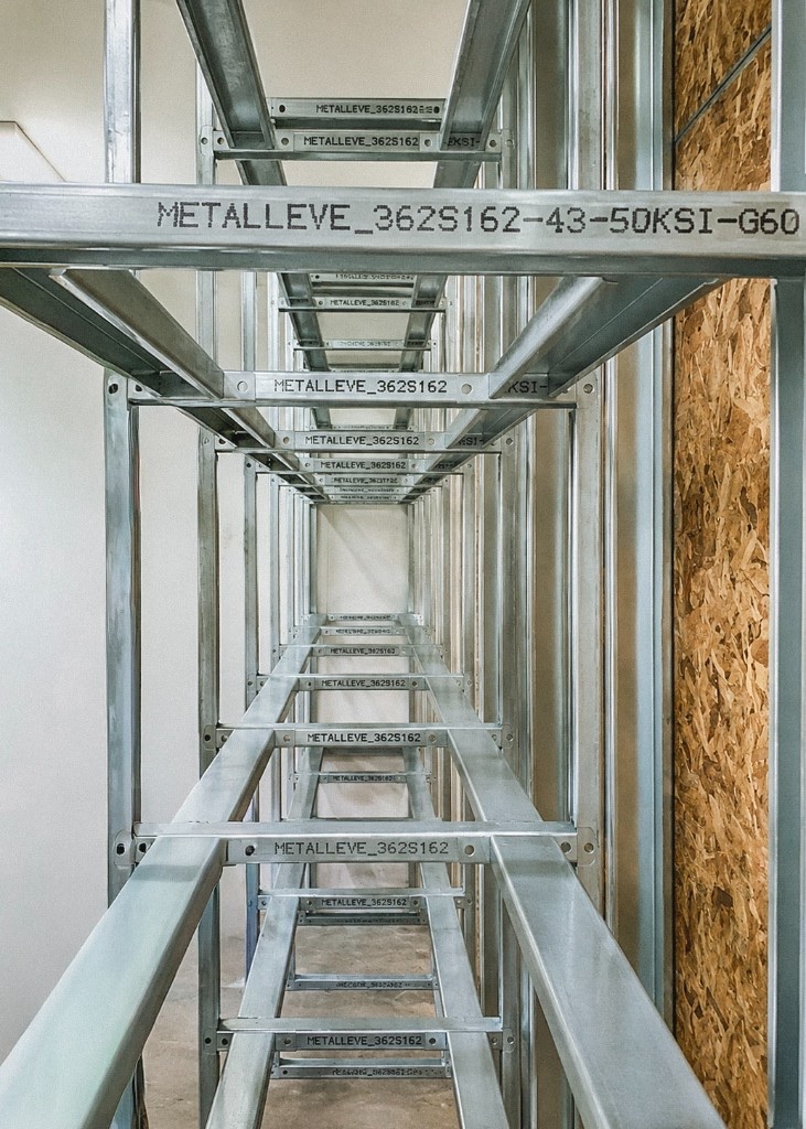
When project information is ready, a roll former can shape members from coil, cut them to length, punch predefined holes, and label them for their location in the framing package.
The members may be sent as organized components for field assembly, or assembled into panels before delivery. Panelization is especially useful when wall geometry, openings, supports, access, lifting, shipping, and installation sequence are resolved early enough to manufacture the assemblies correctly.
The real advantage is repeatability. A resolved wall condition can be produced consistently instead of being measured and improvised again and again in the field.
The Practical Question to Ask First
Before selecting a CFS system, ask: what must this wall, floor, or roof actually do?
The answer should cover loads, supports, height or span, openings, connections, fire and acoustic requirements, thermal strategy, exterior interfaces, delivery format, and installation sequence. Once those questions are answered, the framing system can be detailed and fabricated for the job it needs to perform.
Metalleve Wall Systems supports CFS projects through project review, detailing, FRAMECAD-supported fabrication, components or panelized assemblies, delivery, and installation according to the defined project scope.
Planning a CFS project?
Planning a CFS project in Massachusetts or New England? Send Metalleve your available architectural and structural documents, project location, intended scope, and schedule to begin the framing review.