
Resource
How Cold-Formed Steel Is Fabricated: From Steel Coil to a Structure Ready for Assembly
A cold-formed steel wall can begin to be built before the first piece of steel ever enters the machine.
That is because, in a modern CFS operation, an important part of fabrication first exists as information.
Where will an opening be located? How long will each stud be? Which profile will be used? Where will holes be required? How will the members connect? Which component belongs to which wall?
When those decisions reach production correctly, a steel coil can be transformed into hundreds of different components, each produced for a specific position in the structure.
That is what makes CFS fabrication particularly interesting: it is not simply about forming steel. It is about transforming project information into physical components.
It All Starts With a Coil. But It Is Not Just “Steel”
The material used to manufacture CFS profiles arrives at the fabrication facility as coiled steel.
According to the Steel Framing Industry Association, the upstream industrial process begins with steel produced from iron ore and/or steel scrap. After several steelmaking processes, the material is reduced to sheet and strip that can later feed roll-forming equipment.
But two coils that look similar are not necessarily equivalent.
Thickness, width, mechanical properties, coating, and material specification are all part of the identity of that steel.
This matters because the final profile is not defined only by its shape.
A stud with a particular geometry and thickness should not be treated as interchangeable with another simply because both physically fit in the same wall. Structural design depends on the specified properties of the members and their connections.
In practice, traceability therefore begins before the machine:
Which material entered production?
That seemingly administrative question can become an issue of quality, cost, and traceability.
Before Fabricating Steel, You Have to Fabricate Information
A roll-forming machine does not decide where a window should be.
It also does not know whether a particular stud carries a load, where a header should end, or whether an opening was changed in the latest project revision.
Those decisions happen earlier, during design, engineering, and detailing.
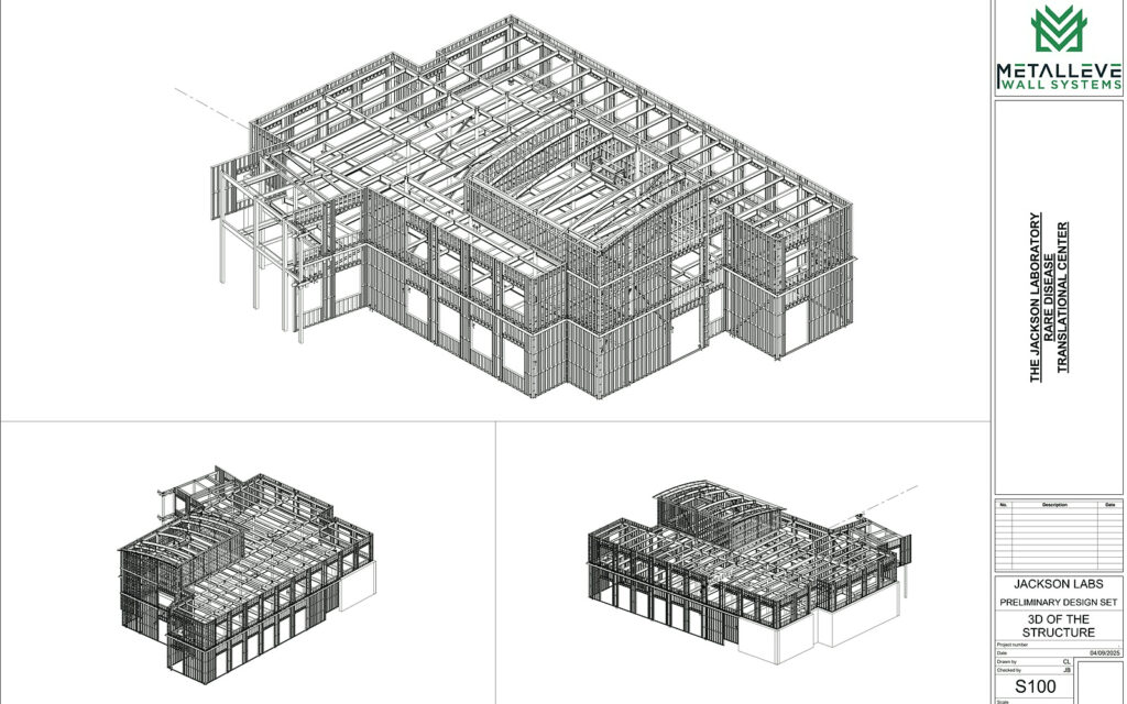
Specialized CFS systems can take this process quite far. FRAMECAD Steelwise documentation, for example, describes tools for wall layout and the engineering of studs, headers, jambs, bracing, roof trusses, and floor systems, as well as the generation of CNC component models and production-ready information.
This is where a fundamental characteristic of digital fabrication appears:
A machine can execute incorrect information with great precision.
If an opening changed in the project but production received the previous revision, manufacturing the member exactly as programmed is not quality.
It is rework manufactured with precision.
That is why revision control is part of the fabrication process, even though it does not physically happen inside the machine.
What Actually Happens Inside a Roll Former?
Imagine a flat strip of steel entering a machine.
It is not simply bent once until it becomes a stud.
The process is progressive.
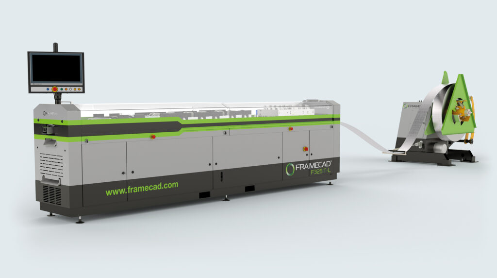
The SFIA explains that structural steel strip passes through a sequence of dies or rolls that gradually form the material into sections such as C, U, Z, and hat-shaped profiles.
A FRAMECAD ST925iT technical manual shows the process in greater detail. Before forming, the material passes through guiding and alignment systems. Different stations then progressively work portions of the profile, including lips and flanges, until the required geometry is achieved. The equipment also provides final adjustments related to profile shape and correction.
That progression matters.
Instead of forcing the entire geometry at once, successive stations gradually transform:
flat strip → initial bends → lips → flanges → final profile.
That is where the name cold-formed steel comes from.
The profile is mechanically formed without heating the steel to create its final geometry.
The Machine Can Do More Than Form the Profile
This may be one of the less obvious parts of the process for someone who has never seen a CFS factory operating.
Producing a stud does not necessarily mean forming one long section, removing it from the machine, measuring it, marking it, making every required hole, and cutting it manually.
Modern equipment can integrate multiple operations into the fabrication flow itself.
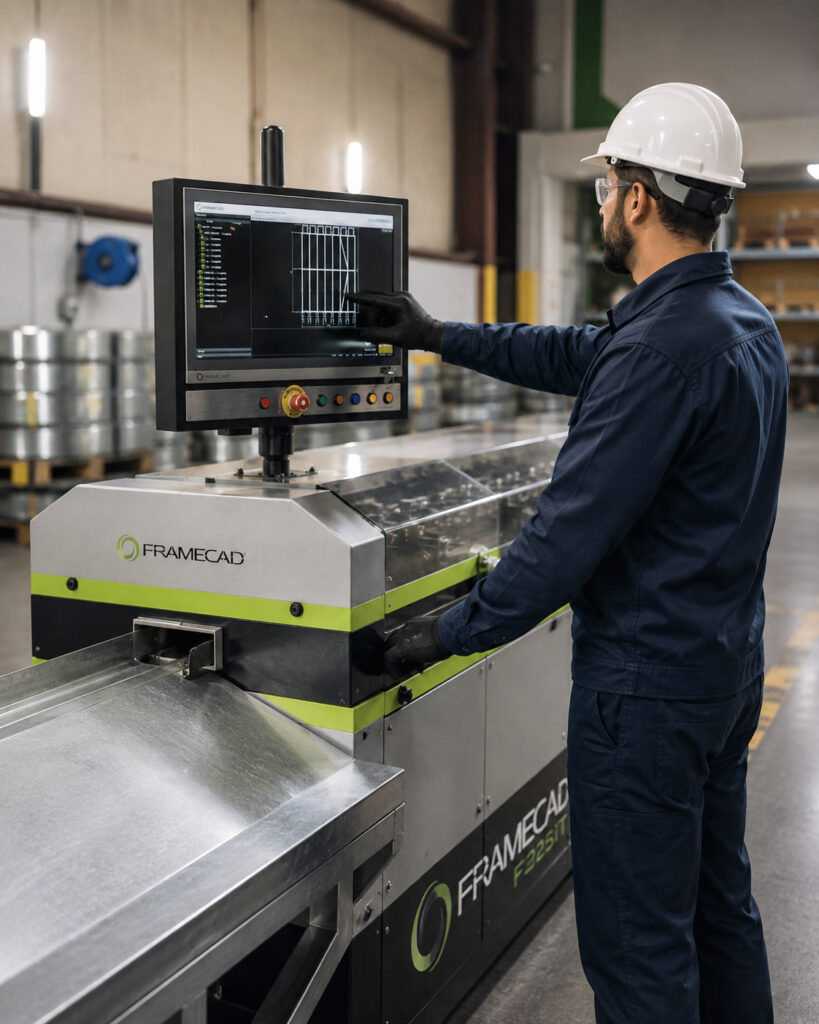
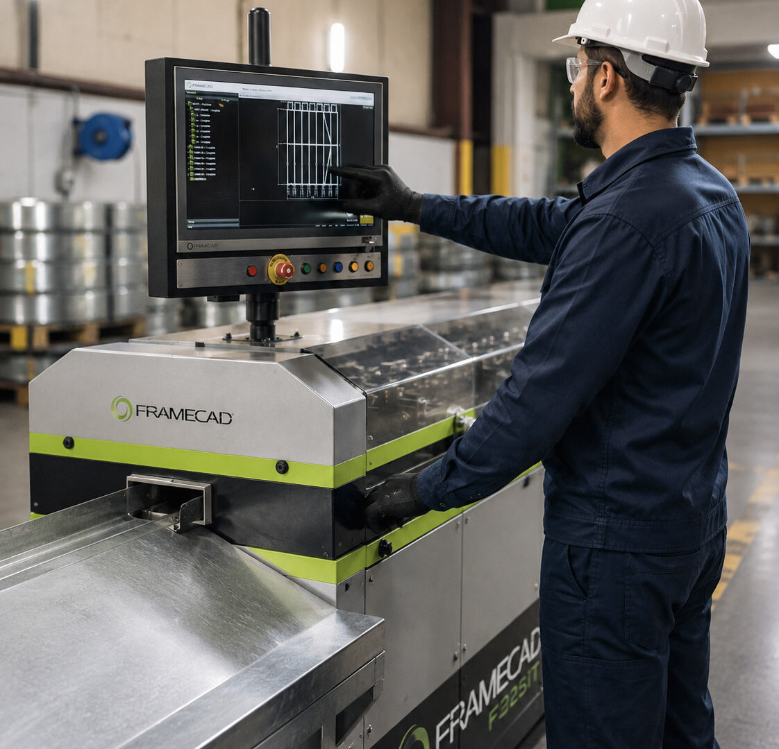
FRAMECAD describes systems capable of punching, cutting, and forming according to digital production data. Depending on the machine and configuration, tooling operations can prepare features required by the component while the material moves through the line.
Equipment designed for specific applications can go even further. The FRAMECAD ST950H, for example, has multiple adjustable roll-forming and punching stations and can manufacture C and U profiles in different dimensions within the machine’s operating range.
This changes the logic of production.
The machine does not necessarily have to manufacture only “a 10-foot stud.”
It can manufacture “the component that belongs in this specific position of this structure.”
The difference is small in the sentence and enormous in the operation.
One Coil Can Become Hundreds of Different Components
This is where CFS begins to resemble manufacturing more than the traditional idea of cutting material at the jobsite.
Consider a wall containing regular studs, top and bottom tracks, jamb studs, members around doors and windows, components associated with headers, members of different lengths, and different tooling operations.
Visually, many of these pieces may still look like metal profiles.
For production, they are not the same.
Each has a function and a position within the assembly.
That is why identification and organization of the components matter just as much as the speed at which they leave the machine.
A factory capable of producing quickly but unable to determine what was produced, for which frame, using which revision and which material has speed without control.
How Fast Does a Machine Like This Actually Run?
There is a temptation here to publish impressive numbers.
Equipment manufacturers publish capacities and speeds for specific machines, but converting nominal roll-former speed into “houses per day” or “panels per hour” usually creates a poor comparison.
Real productivity depends on much more: profile and thickness, tooling operations, material changes, component size and complexity, setup, production organization, assembly, downtime, maintenance, and the quality of the information received.
An extremely fast machine waiting for a project revision is still producing zero.
This is one of the most important ideas for understanding a CFS factory:
Machine speed and factory productivity are not the same thing.
The bottleneck can exist before, inside, or after the roll former.
When the Component Leaves the Machine, Fabrication Is Not Finished
Depending on the project strategy, the components can follow different paths.
One option is to organize the pieces into kits for later assembly.
Another is to assemble frames or panels inside the factory itself.
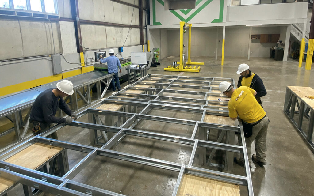
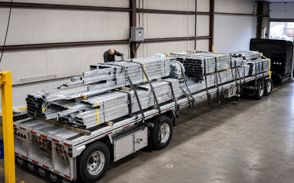
FRAMECAD describes this distinction between assembly and kitting in its manufacturing operations material. After roll forming, components may be assembled in-house or prepared for later assembly. Final checks, stacking, strapping, and staging for transportation follow.
When panelization is used, another transformation takes place.
Studs and tracks stop being individual pieces and become larger assemblies.
That transfers part of the work from the jobsite into a manufacturing environment.
But it creates a new responsibility.
The more work completed before delivery, the more expensive incorrect information can become.
If a critical field dimension is wrong, discovering it before fabrication may be relatively inexpensive. Discovering it after dozens of components have been produced is different. Discovering it when a panel is already at the jobsite is different again.
Prefabrication does not eliminate mistakes.
It increases the value of finding the mistake early.
Quality Control Should Not Exist Only at the End
A simplified view of fabrication might be:
produce everything → inspect → ship.
For structural CFS, quality control goes deeper than a visual inspection at the end.
AISI S240 establishes requirements related to the fabrication and installation of structural framing and contains a dedicated chapter on Quality Control and Quality Assurance. The standard addresses inspection personnel, inspection tasks, and procedures for nonconforming materials or workmanship.
The 2024 International Building Code references AISI S240 for structural CFS light-frame systems, including floor and roof systems, structural walls, lateral systems, and trusses. For certain conditions, the code also establishes additional inspection requirements.
This shows that QC should not answer only: “Does the wall look right?”
Depending on the component and project, control can involve material, dimensions, geometry, connections, fasteners, member locations, documentation, and compliance with approved documents.
And there is an important detail: quality starts before the first screw.
If the wrong material was loaded into the machine, the problem began at material intake.
If the wrong revision was released, it began in the information flow.
If a correct component was placed in the wrong frame, it began with identification.
Fabrication QC is also process control.
Scrap Tells a Story
On the factory floor, discarded pieces of steel may look simply like waste.
But they are also data.
Imagine that a project was expected to consume a certain amount of steel, but production finished using more.
Why?
It could have been normal process scrap, setup, damaged components, fabrication error, a project change, remanufacturing, material used on another project, or a difference between the estimate and actual production.
Without tracking, all of those situations become simply “more steel was used.”
With tracking, an important variable appears:
planned material vs. actual material.
That comparison allows the factory to learn from its own production.
And this is where digital manufacturing becomes more than a computer-controlled machine.
The factory begins producing data about how the factory itself operates.
A Component Has a History Before It Reaches the Jobsite
In a truly traceable operation, it should be possible to reconstruct something close to this chain:
Project → Revision → Frame → Component → Material → Production → QC → Package → Delivery
That answers practical questions.
Which revision generated this component? Which material was used? When was it produced? Did it pass quality control? Which package was it shipped in? If remanufacturing is required, what happened?
Not every factory will have this level of digitalization, and software alone does not guarantee that the process works.
But it is a logical consequence of data-driven fabrication: the more a component originates from digital information, the more sense it makes to preserve its digital history.
The Real Machine Starts Before the Roll Former
It is easy to visit a CFS factory and focus all the attention on the equipment.
The coil turns. The steel enters flat. Tools operate. A formed profile appears on the other side.
It is the visually impressive part.
But the roll former performs only one part of a larger system.
The complete process looks more like:
Design → Engineering → Detailing → Revision Control → Production Data → Coil → Roll Forming → Assembly → Quality Control → Packaging → Delivery
And every arrow matters.
The 2024 IBC makes clear that structural CFS is not simply an informal method of manufacturing metal profiles. The code directs the design and installation of structural light-frame systems to specific standards, including AISI S240.
Fabrication technology can transform a coil into highly specific components.
But it cannot automatically correct a bad decision made before production.
Perhaps the best way to understand a modern CFS factory is this:
A roll former transforms steel into profiles. The process transforms information into a structure.
And the better the connection between those two things, the more predictable fabrication can become.
Planning a CFS project?
Planning a CFS project in Massachusetts or New England? Send Metalleve your available architectural and structural documents, project location, intended scope, and schedule to begin the framing review.